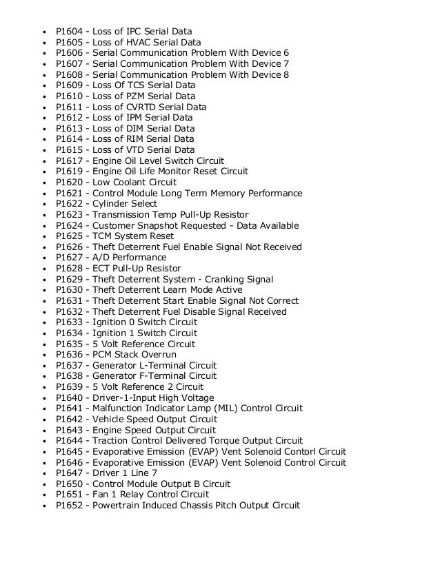
P1607 Serial Communication Problem With Device 7
Repair Information for P1607 Gmc code. Learn what does P1607 Gmc Serial Communication Problem With Device 7 means? Possible Causes and Repair Information for P1607 Gmc code. Learn what does P1607 Gmc means? P1607 Gmc Serial Communication Problem With Device 7.
Loopback Test to Verify Hardware Operation There are three ways to verify the operation of the serial port:, HyperTerminal, and. All perform a loopback test on the serial port by shorting out the Transfer and Receive pins on the cable connected to that port. Step 1 is the description for shorting the pins and is the first step to all three. The procedure is listed below, and both the HyperTerminal and procedures are linked at the end of the page.

Use the following procedure if you are using. • Connect a cable to your serial port. The most common port is a 9-pin or 25-pin (DB-9 or DB-25) RS-232 port. On the cable, short lines 2 and 3. This connects the Transfer line coming out of the computer to the Receive line going in.

Once shorted, the top row of the DB-9 cable should look like this: [1 2=3 4 5]. Oz Season 2 Torrent Download more. An easy way to short pins 2 and 3 is to use a paper clip. If you have a female RS-232 cable, bend the paper clip and stick the ends in the second and third hole.
If you have a male cable, bend the paper clip in a way that you shorten the long loop to the same length as the short loop. Then you can clamp it on the two pins. On an RS-485 port, voltages are referenced differentially. Therefore, short TXD+ and RXD+ together and then TXD- and RXD- together (pin 4 to 8 and pin 5 to 9 on a DB-9 cable; pin 1 to 5 and pin 2 to 4 on a Combicon connector).
Make sure your software is configured in four-wire mode. • For HyperTerminal or LabWindows/CVI, follow the links at the end of the page. • For, follow the link 'Loopback Test for Serial Port.' This takes you to the Loopback VI in the Example Program Database, which is a part of the Technical Support page. You need to unzip the file.
This VI is written in LabVIEW 4.0.1 and will write a string of words out of the serial port and then read them back in. Before running the VI, make sure to set the port channel correctly. In LabVIEW, zero represents the first serial port.
[PC: 0 = COM1, 1 = COM2. Mac: 0 = Modem, 1 = Printer. Sun: 0 = ttya, 1 = ttyb.] • If this works correctly and the string of words is read back in, the serial port hardware works. Most serial port communication problems are in the program and concern timing of read/writes calls or configuration of the serial port.
Common Problems Most problems are in the program, not the hardware. Always use example programs as a reference point for ways to wire the diagram panel. Use the sample VIs shipped with under Help>>Search Examples or from the VIs located in the Examples Program Database linked at the end of the page. Port Referencing: In LabVIEW, ports are numbered starting at zero.
Therefore, port 0 in LabVIEW is COM 1 on a PC. [PC: 0 = COM1, 1= COM2. Mac: 0 = Modem, 1 = Printer. Sun: 0 = ttya, 1 = ttyb.] Timing In Program, Hanging: Many times, a read operation is performed on a port that results in the Serial Port Read VI stopping and waiting or 'hanging.'
One way this can happen is if a read operation is done to the port and the program specifies a certain number of bytes that the Serial Port Read VI should get. The Serial Port Read VI was told to get a designated number of bytes; if there are not that many bytes in the serial port receive buffer, it waits until more bytes are written to the serial port. If no more bytes are written to the serial port to complete the operation, the program hangs and waits indefinitely.